Pipecheck features several minor functionalities that are not well-known yet, but end up being very useful. Let’s have a look at 3 of them.
Standard Views
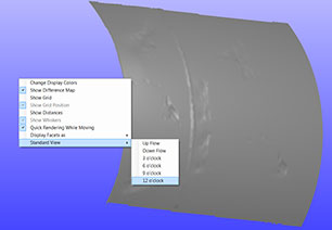
The user can automatically display the pipe in 6 different standard views in the 3D scene, which is helpful. This helps proceeding further operations or analysis:
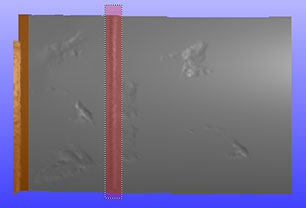
- Makes it easier to select some areas (welds) with the rectangle selection tool.
- Makes it easier to see which circumferential position the user is looking at for a complete pipe
To get there:
- Right click and select Standard Views;
- Left click to select the desired standard view.
Zoom out and lose the part
If you zoomed out too much and moved your part in the 3D scene, you might end up not being able to recover a good display position. Even if you use the 6 standard views, the software will only center the pipe without zooming in. Tip: to recover a better view of the pipe, select a feature in the treeview. Pipecheck will automatically center and fit the pipe in the 3D scene.
To use this functionality:
- expand the Feature tab in the treeview (after an analysis);
- left click on any feature.
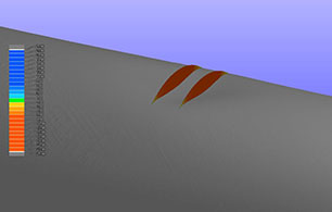
Create Shoulders
In the Mechanical Damage module, you can now ask Pipecheck to automatically create 2 circumferential cross-sections, named Shoulders, at a defined distance from the deepest point of the feature. One cross-section will be created on each side of the deepest point along the axial axis.
To use this feature:
- Left click on Parameters in the toolbar
- Left click on Mechanical Damage tab on the left
- In the Analysis tab, check Create Shoulders and enter a desired distance from deepest points.